Printed (wiring) circuit boards are given targeted electronic circuit functions by forming conductor wiring on insulating plates (glass-substrate heat-resistant resin copper-clad laminates or the like) and connecting various functional electrical components (ICs, chip parts, etc.) here. Thanks to solder plating and gold plating, wiring and connections between these various electronic microparts are enabled. There are hard (green) and soft (brown) printed circuit boards as shown below. The former is called rigid circuit boards, and the latter is called flexible circuit boards.
| Type | Characteristic value & uses |
|---|---|
| 1 conductor layer | - Rigid (single-faced circuit board) - Flexible (1-metal layer circuit board: 2-layer type, 3-layer type) |
| 2 conductor layers | - Rigid (double-faced circuit board) Plated-throughhole printed wiring board - Flexible (plated-throughhole printed wiring board) |
| Multiple-conductor layers | - Rigid |
(From “Purinto Haisenban no Dekirumade” by Kiyoshi Takagi; Nikkan Kogyo Shimbun Ltd.)
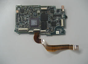
Printed circuit board including LSI and electronic parts
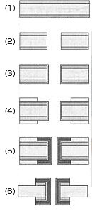 Manufacturing process of throughhole plating for conduction from the front side to the back side of printed wiring boards (subtractive method):